| Series | Volute | Volute | Seal Type | Flow Range (GPM) | Head Range (ft) | Hp Rang | Suc. x Disch. |
|---|---|---|---|---|---|---|---|
| DR1S-CP | CI | PL | 1 | 20-60 | 30-105 | 1/2-1 | 1.25″ x 1.00″ |
| DR1S-SP | SS | PL | 1 | 20-60 | 33-115 | 1/2-1 | 1.25″ x 1.00″ |
| DR1C-CP | CI | PL | 2 | 20-60 | 25-100 | 1/2-1 | 1.25″ x 1.00″ |
| DR1C-SS | SS | SS | 2 | 20-60 | 22-107 | 1/2-1 | 1.25″ x 1.00″ |
| DR1J-CS | CI | SS | 2 | 20-60 | 20-105 | 1/2-1 | 1.25″ x 1.00″ |
| DR2S-CS | CI | SS | 1 | 30-90 | 25-127 | 1-2 | 1.50″ x 1.25″ |
| DR2C-CS | CI | SS | 2 | 30-90 | 23 – 123 | 1-2 | 1.50″ x 1.25″ |
| DR2J-CS | CI | SS | 2 | 30-90 | 25-133 | 1/2-1 | 1.50″ x 1.25″ |
| DR1S-CP | HP | PEI | Volute | Impeller | Seal Type | Fluid Max °F | Capacity in GPM at Total Feet of Head Indicated | Max Press. (PSI) | |||||||||
|---|---|---|---|---|---|---|---|---|---|---|---|---|---|---|---|---|---|
| 30 | 40 | 50 | 60 | 70 | 80 | 90 | 100 | 110 | 120 | ||||||||
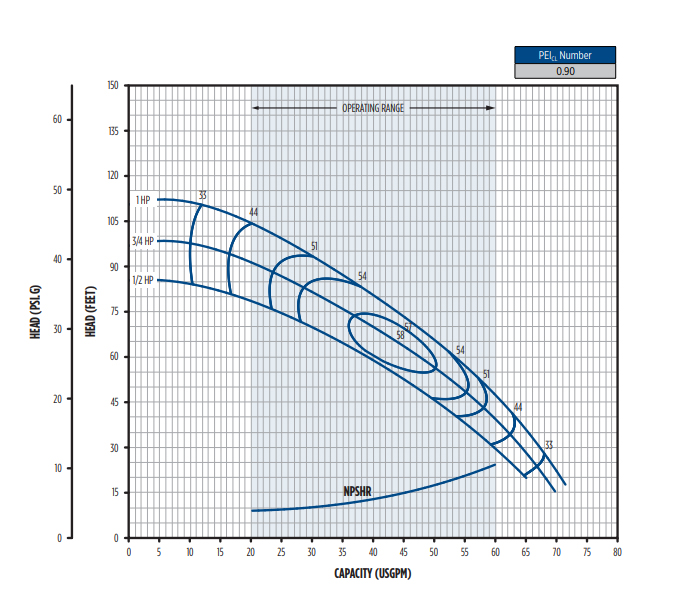
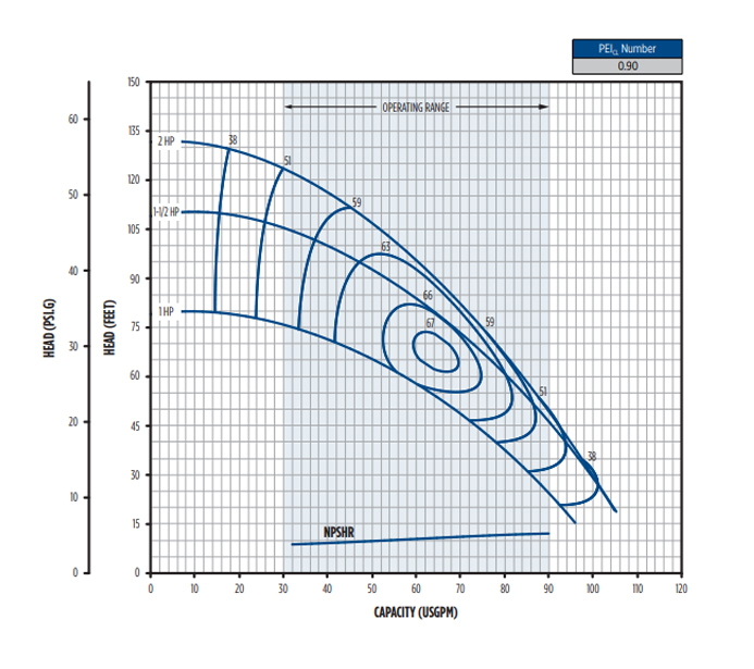
| DR1S05-CP | 1/2 | 0.90 | CI | PL | 1 | 120 | 59.3 | 53.3 | 46.6 | 38.9 | 29.5 | – | – | – | – | – | 37.0 |
| DR1S07-CP | 3/4 | 0.90 | CI | PL | 1 | 120 | 63.9 | 58.9 | 53.5 | 47.5 | 40.6 | 32.3 | 20.9 | – | – | – | 42.0 |
| DR1S1-CP | 1 | 0.90 | CI | PL | 1 | 120 | 63.2 | 58.4 | 53.2 | 47.4 | 40.9 | 33.3 | 23.7 | – | – | 48.0 | |
| Enclosure | RPM | Phase | Volage | Hp | S.F | S.F. Amps | Imp. Dia. | Order No. | Model No. | Wt. (lbs) | ||
|---|---|---|---|---|---|---|---|---|---|---|---|---|
| 115 | 230 | 460 | ||||||||||
| ODP | 3600 | 1 | 115/230 | 1/2 | 1.90 | 12.4 | 6.1 | – | 4.70 | 97110005 | DR1S05-CP | 36 |
| 3/4 | 1.65 | 14.8 | 7.3 | – | 5.00 | 97110007 | DR1S07-CP | 39 | ||||
| 1 | 1.65 | 19.9 | 9.9 | – | 5.36 | 97110010 | DR1S1-CP | 43 | ||||
| 3 | 230/460 | 1/2 | 1.90 | – | 3.1 | 1.4 | 4.70 | 97113005 | DR1S05-CP-T | 35 | ||
| 3/4 | 1.65 | – | 3.6 | 1.7 | 5.00 | 97113007 | DR1S07-CP-T | 38 | ||||
| 1 | 1.65 | – | 4.7 | 2.3 | 5.36 | 97113010 | DR1S1-CP-T | 40 | ||||
| Volute | CI | Cast Iron, ASTM-A48, Class 30, 1-1/4″ x 1″ |
|---|---|---|
| Impeller | PL | Polyphenylene Ether Polystyrene Modified (PPE+PS 30%GF) |
| Mechanical Seal Types | 1 | Phenolic x Ceramic x Nitrile x SS |
| Motor Confugurations | 48Y | Square Flange with 1/2″ threaded SS shaft, impeller mounts directly on motor shaft |
| DR1S-SP | HP | PEI | Volute | Impeller | Seal Type | Fluid Max °F | Capacity in GPM at Total Feet of Head Indicated | Max Press. (PSI) | |||||||||
|---|---|---|---|---|---|---|---|---|---|---|---|---|---|---|---|---|---|
| 30 | 40 | 50 | 60 | 70 | 80 | 90 | 100 | 110 | 120 | ||||||||
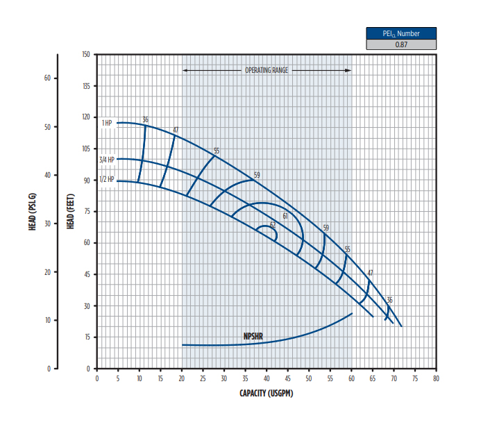
| DR1S05-SP | 1/2 | .87 | SS | PL | 1 | 120 | 61.4 | 55.9 | 49.7 | 42.7 | 34.5 | – | – | – | – | – | 38.4 |
| DR1S07-SP | 3/4 | 0.87 | SS | PL | 1 | 120 | 65.7 | 60.6 | 55.2 | 49.1 | 42.2 | 33.9 | 23.0 | – | – | – | 42.8 |
| DR1S1-SP | 1 | .87 | SS | PL | 1 | 120 | – | 65.4 | 60.6 | 55.4 | 49.8 | 43.7 | 36.9 | 28.9 | – | – | 50.1 |
| Enclosure | RPM | Phase | Volage | Hp | S.F | S.F. Amps | Imp. Dia. | Order No. | Model No. | Wt. (lbs) | ||
|---|---|---|---|---|---|---|---|---|---|---|---|---|
| 115 | 230 | 460 | ||||||||||
| ODP | 3600 | 1 | 115/230 | 1/2 | 1.90 | 12.4 | 6.1 | – | 4.70 | 97110105 | DR1S05-SP | 35 |
| 3/4 | 1.65 | 14.8 | 7.3 | – | 5.00 | 97110107 | DR1S07-SP | 38 | ||||
| 1 | 1.65 | 19.9 | 9.9 | – | 5.36 | 97110110 | DR1S1-SP | 42 | ||||
| 3 | 230/460 | 1/2 | 1.90 | – | 3.1 | 1.4 | 4.70 | 97113105 | DR1S05-SP-T | 34 | ||
| 3/4 | 1.65 | – | 3.6 | 1.7 | 5.00 | 97113107 | DR1S07-SP-T | 37 | ||||
| 1 | 1.65 | – | 4.7 | 2.3 | 5.36 | 97113110 | DR1S1-SP-T | 39 | ||||
| Volute | SS | Stainless steel, 1-1/4″ x 1″ |
| Impeller | PL | Polyphenylene Ether Polystyrene Modified (PPE+PS 30%GF) |
| Mechanical Seal Types | 1 | Phenolic x Ceramic x Nitrile x SS |
| Motor Confugurations | 48Y | Square Flange with 1/2″ threaded SS shaft, impeller mounts directly on motor shaft |
| DR1C-CP | HP | PEI | Volute | Impeller | Seal Type | Fluid Max °F | Capacity in GPM at Total Feet of Head Indicated | Max Press. (PSI) | |||||||||
|---|---|---|---|---|---|---|---|---|---|---|---|---|---|---|---|---|---|
| 30 | 40 | 50 | 60 | 70 | 80 | 90 | 100 | 110 | 120 | ||||||||
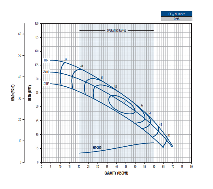
| DR1C05-CP | 1/2 | 0.96 | CI | PL | 2 | 120 | 57.1 | 51.0 | 44.1 | 36.2 | 26.5 | – | – | – | – | – | 36.6 |
| DR1C07-CP | 3/4 | 0.96 | CI | PL | 2 | 120 | 63.7 | 58.5 | 52.9 | 46.6 | 39.4 | 30.8 | 18.9 | – | – | – | 42.0 |
| DR1C1-CP | 1 | 0.96 | CI | PL | 2 | 120 | – | 62.1 | 56.9 | 51.3 | 45.2 | 38.4 | 30.7 | 21.4 | – | – | 47.3 |
| Enclosure | RPM | Phase | Volage | Hp | S.F | S.F. Amps | Imp. Dia. | Order No. | Model No. | Wt. (lbs) | ||
|---|---|---|---|---|---|---|---|---|---|---|---|---|
| 115 | 230 | 460 | ||||||||||
| ODP | 3600 | 1 | 115/230 | 1/2 | 1.60 | 11.8 | 5.9 | – | 4.70 | 97150005 | DR1C05-CP | 43 |
| 3/4 | 1.50 | 14.8 | 7.4 | – | 5.00 | 97150007 | DR1C07-CP | 45 | ||||
| 1 | 1.40 | 16.8 | 8.4 | – | 5.36 | 97150010 | DR1C1-CP | 49 | ||||
| Volute | CI | Cast Iron, ASTM-A48, Class 30, 1-1/4″ x 1″ |
| Impeller | PL | Polyphenylene Ether Polystyrene Modified (PPE+PS 30%GF) |
| Mechanical Seal Types | 2 | GL-SiC x GL-SiC x FKM x SS |
| Motor Confugurations | 56C | Round flange – keyed shaft, impeller mounts to shaft coupling with 1/2″ threads |
| DR1C-SS | HP | PEI | Volute | Impeller | Seal Type | Fluid Max °F | Capacity in GPM at Total Feet of Head Indicated | Max Press. (PSI) | |||||||||
|---|---|---|---|---|---|---|---|---|---|---|---|---|---|---|---|---|---|
| 30 | 40 | 50 | 60 | 70 | 80 | 90 | 100 | 110 | 120 | ||||||||
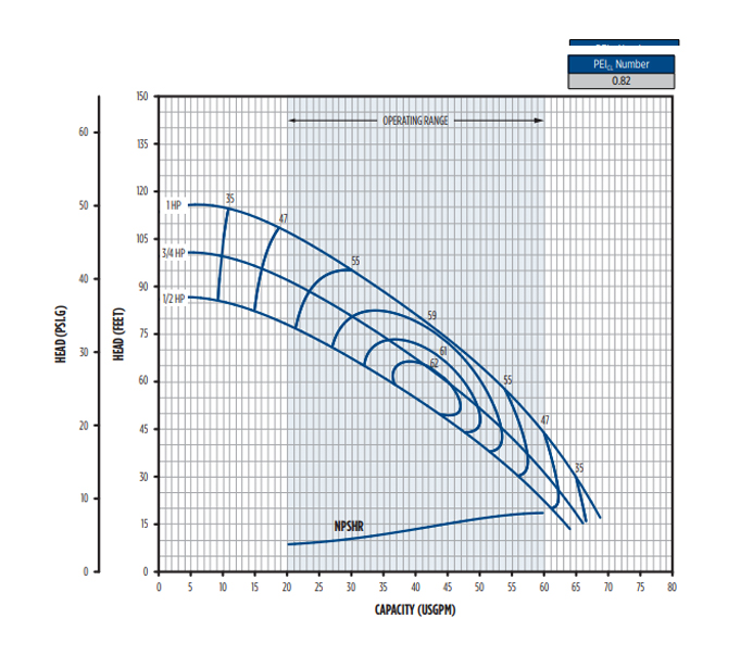
| DR1C05-SS | 1/2 | 0.82 | SS | SS | 2 | 180 | 55.8 | 50.1 | 43.8 | 36.7 | 28.0 | – | – | – | – | – | 37.3 |
| DR1C07-SS | 3/4 | 0.82 | SS | SS | 2 | 180 | 60.9 | 55.9 | 50.6 | 44.7 | 38.2 | 30.8 | 21.9 | – | – | 43.2 | |
| DR1C1-SS | 1 | 0.82 | SS | SS | 2 | 180 | – | 61.8 | 57.2 | 52.2 | 46.8 | 40.9 | 34.3 | 26.5 | – | – | 49.2 |
| Enclosure | RPM | Phase | Volage | Hp | S.F | S.F. Amps | Imp. Dia. | Order No. | Model No. | Wt. (lbs) | |||
|---|---|---|---|---|---|---|---|---|---|---|---|---|---|
| 115 | 230 | 460 | 575 | ||||||||||
| ODP | 3600 | 1 | 115/230 | 1/2 | 1.60 | 11.8 | 5.9 | – | – | 4.70 | 97150305 | DR1C05-SS | 43 |
| 3/4 | 1.50 | 14.8 | 7.4 | – | – | 5.00 | 97150307 | DR1C07-SS | 45 | ||||
| 1 | 1.40 | 16.8 | 8.4 | – | – | 5.36 | 97150310 | DR1C1-SS | 49 | ||||
| TEFC | 3600 | 1 | 115/230 | 3/4 | 1.15 | 10.8 | 5.4 | – | – | 4.70 | 97151305 | DR1C05-SS-SE | 52 |
| 1 | 1.15 | 13.8 | 6.9 | – | – | 5.00 | 97151307 | DR1C07-SS-SE | 54 | ||||
| 1-1/2 | 1.15 | 18.4 | 9.2 | – | – | 5.36 | 97151310 | DR1C1-SS-SE | 63 | ||||
| 3 | 230/460 | 3/4 | 1.15 | – | 2.6 | 1.3 | – | 4.70 | 97154305 | DR1C05-SS-TE | 53 | ||
| 1 | 1.15 | – | 3.2 | 1.6 | – | 5.00 | 97154307 | DR1C07-SS-TE | 56 | ||||
| 1-1/2 | 1.15 | – | 5.2 | 2.6 | – | 5.36 | 97154310 | DR1C1-SS-TE | 60 | ||||
| 3 | 575 | 3/4 | 1.15 | – | – | – | 0.8 | 4.70 | 97155305 | DR1C05-SS-T5E | 53 | ||
| 1 | 1.15 | – | – | – | 1.3 | 5.00 | 97155307 | DR1C07-SS-T5E | 56 | ||||
| 1-1/2 | 1.15 | – | – | – | 1.9 | 5.36 | 97155310 | DR1C1-SS-T5E | 60 | ||||
| Volute | SS | Stainless steel |
| Impeller | SS | Stainless steel |
| Mechanical Seal Types | 2 | GL-SiC x GL-SiC x FKM x SS |
| Motor Confugurations | 56C | Round flange – keyed shaft, impeller mounts to shaft coupling with 1/2″ threads |
| DR1J-CS | HP | PEI | Volute | Impeller | Seal Type | Fluid Max °F | Capacity in GPM at Total Feet of Head Indicated | Max Press. (PSI) | |||||||||
|---|---|---|---|---|---|---|---|---|---|---|---|---|---|---|---|---|---|
| 30 | 40 | 50 | 60 | 70 | 80 | 90 | 100 | 110 | 120 | ||||||||
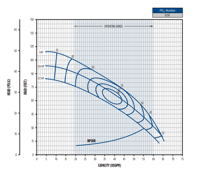
| DR1J05-CS | 1/2 | 1.00 | CI | SS | 2 | 160 | 54.7 | 48.8 | 42.2 | 34.8 | 25.9 | – | – | – | – | – | 36.5 |
| DR1J07-CS | 3/4 | 1.00 | CI | SS | 2 | 160 | 60.4 | 55.7 | 50.5 | 44.8 | 38.2 | 30.4 | 20.0 | – | – | – | 42.4 |
| DR1J1-CS | 1 | 1.00 | CI | SS | 2 | 160 | – | 58.3 | 54.3 | 50.0 | 45.2 | 39.8 | 33.4 | 25.2 | – | – | 48.4 |
| Enclosure | RPM | Phase | Volage | Hp | S.F | S.F. Amps | Imp. Dia. | Order No. | Model No. | Wt. (lbs) | ||
|---|---|---|---|---|---|---|---|---|---|---|---|---|
| 115 | 230 | 460 | ||||||||||
| ODP | 3600 | 1 | 115/230 | 1/2 | 1.60 | 11.8 | 5.9 | – | 4.70 | 97120205 | DR1J05-CS | 39 |
| 3/4 | 1.50 | 14.8 | 7.4 | – | 5.00 | 97120207 | DR1J07-CS | 41 | ||||
| 1 | 1.40 | 16.2 | 8.1 | – | 5.36 | 97120210 | DR1J1-CS | 44 | ||||
| 1 | 230/460 | 1/2 | 1.60 | – | 2.7 | 1.4 | 4.70 | 97123205 | DR1J05-CS-T | 38 | ||
| 3/4 | 1.50 | – | 3.4 | 1.7 | 5.00 | 97123207 | DR1J07-CS-T | 41 | ||||
| 1 | 1.40 | – | 4.0 | 2.0 | 5.36 | 97123210 | DR1J1-CS-T | 44 | ||||
| Volute | CI | Cast Iron, ASTM-A48, Class 30, 1-1/4″ x 1″ |
| Impeller | SS | Stainless steel |
| Mechanical Seal Types | 2 | GL-SiC x GL-SiC x FKM x SS |
| Motor Confugurations | 56C | Round flange with 7/16″ threaded shaft, impeller mounts directly on motor shaft |
| DR2S-CS | HP | PEI | Volute | Impeller | Seal Type | Fluid Max °F | Capacity in GPM at Total Feet of Head Indicated | Max Press. (PSI) | |||||||||
|---|---|---|---|---|---|---|---|---|---|---|---|---|---|---|---|---|---|
| 30 | 40 | 50 | 60 | 70 | 80 | 90 | 100 | 110 | 120 | ||||||||
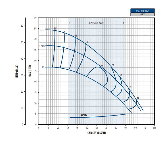
| DR2S1-CS | 1 | 0.83 | CI | SS | 1 | 120 | 86.6 | 78.7 | 69.8 | 59.2 | 45.4 | – | – | – | – | – | 34.5 |
| DR2S15-CS | 1-1/2 | 0.83 | CI | SS | 1 | 120 | 94.3 | 88.1 | 81.4 | 73.9 | 65.5 | 55.4 | 42.4 | – | – | 47.4 | |
| DR2S2-CS | 2 | 0.83 | CI | SS | 1 | 120 | – | – | 93.3 | 87.8 | 82.0 | 75.7 | 68.8 | 61.0 | 51.9 | 40.5 | 57.3 |
| Enclosure | RPM | Phase | Volage | Hp | S.F | S.F. Amps | Imp. Dia. | Order No. | Model No. | Wt. (lbs) | ||
|---|---|---|---|---|---|---|---|---|---|---|---|---|
| 115 | 230 | 460 | ||||||||||
| ODP | 3600 | 1 | 115/230 | 1/2 | 1.65 | 19.9 | 9.9 | – | 4.56 | 97130210 | DR2S1-CS | 46 |
| 1-1/2 | 1.47 | 24.0 | 12.1 | – | 5.25 | 97130215 | DR2S15-CS | 46 | ||||
| 230 | 2 | 1.30 | – | 11.2 | – | 5.75 | 97130220 | DR2S2-CS | 54 | |||
| 3 | 230/460 | 1 | 1.65 | – | 4.7 | 2.3 | 4.56 | 97133210 | DR2S1-CS-T | 43 | ||
| 1-1/2 | 1.47 | – | 6.8 | 3.3 | 5.25 | 97133215 | DR2S15-CS-T | 47 | ||||
| 2 | 1.30 | – | 8.5 | 4.2 | 5.75 | 97133220 | DR2S2-CS-T | 49 | ||||
| Volute | CI | Cast Iron, ASTM-A48, Class 30, 1-1/4″ x 1″ |
| Impeller | SS | Stainless steel |
| Mechanical Seal Types | 1 | Phenolic x Ceramic x Nitrile x SS |
| Motor Confugurations | 48Y | Square Flange with 1/2″ threaded SS shaft, impeller mounts directly on motor shaft |
| DR2C-CS | HP | PEI | Volute | Impeller | Seal Type | Fluid Max °F | Capacity in GPM at Total Feet of Head Indicated | Max Press. (PSI) | |||||||||
|---|---|---|---|---|---|---|---|---|---|---|---|---|---|---|---|---|---|
| 30 | 40 | 50 | 60 | 70 | 80 | 90 | 100 | 110 | 120 | ||||||||
| DR2C1-CS | 0.9 | CI | SS | 2 | 180 | 56C | 86 | 78 | 68 | 57 | 43 | – | – | – | – | – | 34 |
| DR2C15-CS | 0.9 | CI | SS | 2 | 180 | 56C | – | 93 | 87 | 80 | 73 | 64 | 54 | 40 | – | – | 47 |
| DR2C2-CS | 0.9 | CI | SS | 2 | 180 | 56C | – | – | 90 | 84 | 78 | 72 | 64 | 56 | 47 | 35 | 57 |
| Enclosure | RPM | Phase | Volage | Hp | S.F | S.F. Amps | Imp. Dia. | Order No. | Model No. | Wt. (lbs) | |||
|---|---|---|---|---|---|---|---|---|---|---|---|---|---|
| 115 | 230 | 460 | 575 | ||||||||||
| ODP | 3600 | 1 | 115/230 | 1 | 1.40 | 16.2 | 8.1 | – | – | 4.56 | 97160210 | DR2C1-CS | 46 |
| 1-1/2 | 1.30 | 21.4 | 10.7 | – | – | 5.25 | 97160215 | DR2C15-CS | 55 | ||||
| 230 | 2 | 1.40 | – | 12.9 | – | – | 5.75 | 97160220 | DR2C2-CS | 54 | |||
| TEFC | 3600 | 1 | 115/230 | 1-1/2 | 1.25 | 18.4 | 9.2 | – | – | 4.56 | 97161210 | DR2C1-CS-SE | 60 |
| 230 | 2 | 1.15 | – | 10.0 | – | – | 5.25 | 97161215 | DR2C15-CS-SE | 69 | |||
| 3 | 1.15 | – | 14.6 | – | – | 5.75 | 97161220 | DR2C2-CS-SE | 70 | ||||
| 3 | 230/460 | 1-1/2 | 1.15 | – | 5.2 | 2.6 | – | 4.56 | 97164210 | DR2C1-CS-TE | 57 | ||
| 2 | 1.15 | – | 6.0 | 3.0 | – | 5.25 | 97164215 | DR2C15-CS-TE | 67 | ||||
| 3 | 1.15 | – | 7.7 | 3.9 | – | 5.75 | 97164220 | DR2C2-CS-TE | 71 | ||||
| 3 | 575 | 1-1/2 | 1.25 | – | – | – | 1.9 | 4.56 | 97165210 | DR2C1-CS-T5E | 57 | ||
| 2 | 1.25 | – | – | – | 2.4 | 5.25 | 97165215 | DR2C15-CS-T5E | 67 | ||||
| 3 | 1.25 | – | – | – | 3.6 | 5.75 | 97165220 | DR2C2-CS-T5E | 71 | ||||
| Volute | CI | Cast Iron, ASTM-A48, Class 30, 1-1/2″ x 1-1/4″ |
| Impeller | SS | Stainless steel |
|---|---|---|
| Mechanical Seal Types | 2 | GL-SiC x GL-SiC x FKM x SS |
| Motor Confugurations | 56C | Round flange – keyed shaft, impeller mounts to shaft coupling with 1/2″ threads |
| DR2J-CS | HP | PEI | Volute | Impeller | Seal Type | Fluid Max °F | Capacity in GPM at Total Feet of Head Indicated | Max Press. (PSI) | |||||||||
|---|---|---|---|---|---|---|---|---|---|---|---|---|---|---|---|---|---|
| 30 | 40 | 50 | 60 | 70 | 80 | 90 | 100 | 110 | 120 | ||||||||
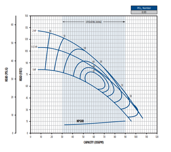
| DR2J1-CS | 1 | 0.93 | CI | SS | 2 | 160 | 86.0 | 78.4 | 69.8 | 59.6 | 46.4 | – | – | – | – | – | 34.9 |
| DR2J15-CS | 1-1/2 | 0.93 | CI | SS | 2 | 160 | – | 94.9 | 88.3 | 81.1 | 73.1 | 64.1 | 53.3 | 39.3 | – | – | 47.0 |
| DR2J2-CS | 2 | 0.93 | CI | SS | 2 | 160 | – | – | 90.8 | 85.1 | 78.9 | 72.2 | 64.9 | 56.5 | 46.7 | 34.2 | 57.1 |
| Enclosure | RPM | Phase | Volage | Hp | S.F | S.F. Amps | Imp. Dia. | Order No. | Model No. | Wt. (lbs) | ||
|---|---|---|---|---|---|---|---|---|---|---|---|---|
| 115 | 230 | 460 | ||||||||||
| ODP | 3600 | 1 | 115/230 | 1 | 1.40 | 16.2 | 8.1 | – | 4.56 | 97140210 | DR2J1-CS | 46 |
| 1-1/2 | 1.30 | 21.4 | 10.7 | – | 5.25 | 97140215 | DR2J15-CS | 55 | ||||
| 230 | 2 | 1.40 | – | 12.9 | – | 5.75 | 97140220 | DR2J2-CS | 54 | |||
| 3 | 230/460 | 1 | 1.40 | – | 4.0 | 2.0 | 4.56 | 97143210 | DR2J1-CS-T | 46 | ||
| 1-1/2 | 1.30 | – | 6.8 | 3.4 | 5.25 | 97143215 | DR2J15-CS-T | 50 | ||||
| 2 | 1.30 | – | 8.5 | 4.2 | 5.75 | 97133220 | DR2S2-CS-T | 49 | ||||
| Volute | CI | Cast Iron, ASTM-A48, Class 30, 1-1/2″ x 1-1/4″ |
| Impeller | SS | Stainless steel |
|---|---|---|
| Mechanical Seal Types | 2 | GL-SiC x GL-SiC x FKM x SS |
| Motor Confugurations | 56J | Round flange with 7/16″ threaded shaft, impeller mounts directly on motor shaft |
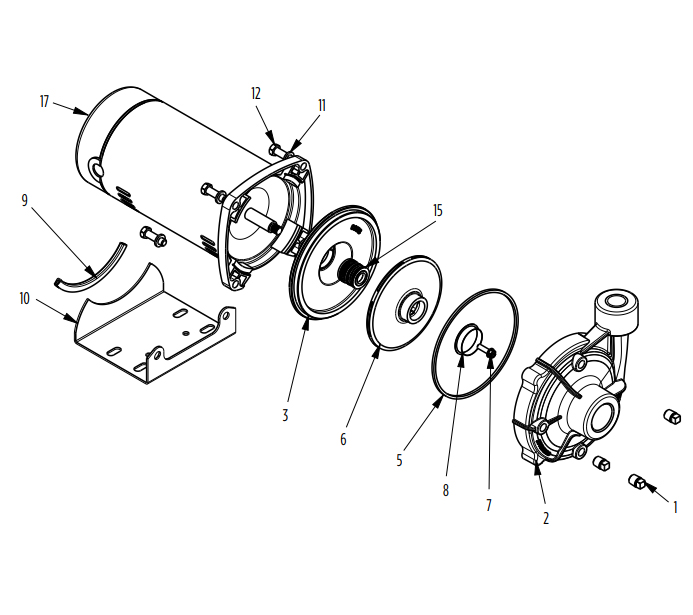
| Fig. No. | Part Description | Order No. | |
|---|---|---|---|
| DR1J-CS | DR2J-CS | ||
| 1, 2 | Volute, Includes Pipe Plugs | 305617102 | 305617201 |
| 4 | Bracket 56J | 305617105 | |
| 5 | Volute Case Square Ring | 305373908 | |
| 6, 8 | Impeller & Wear Ring 1/2 HP | 305617109 | – |
| 6, 8 | Impeller & Wear Ring 3/4 HP | 305617110 | – |
| 6, 8 | Impeller & Wear Ring 1 HP | 305617111 | 305617205 |
| 6, 8 | Impeller & Wear Ring 1-1/2 HP | – | 305617206 |
| 6, 8 | Impeller & Wear Ring 2 HP | – | 305617207 |
| 8 | Wear Ring | 305373906 | 305617208 |
| 9 | Base Protector | 305373905 | |
| 9, 10 | Base, Includes Protector | 305373904 | |
| 1,13,14 | Hardware Kit | 305617002 | |
| 13 | Bolt 3/8″ x 0.88″ (qty. 8) | See Hardware Kit | |
| 14 | Washer 3/8″ (qty. 2) | ||
| 16 | Shaft Seal | 305421004 | |
| 17 | Motor (See Motor Specifications) | 56C | |
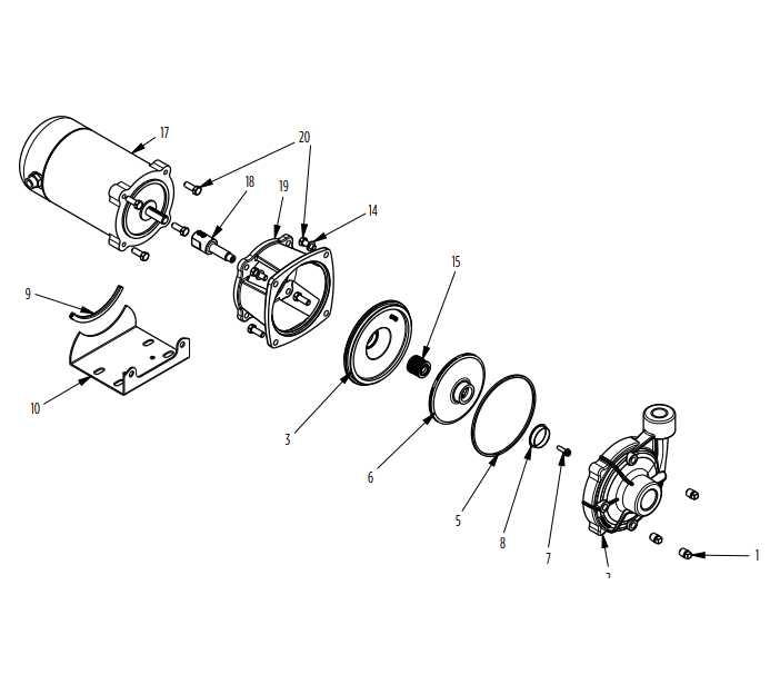
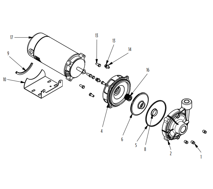
| Fig. No. | Part Description | Order No. | ||
|---|---|---|---|---|
| DR1C-SS | DR1C-CP | DR2C-CS | ||
| 1, 2 | Volute, Includes Pipe Plugs | 305617101 | 305617102 | 305617201 |
| 3 | Seal Plate | 305617103 | 305617104 | |
| 5 | Square Ring | 305373908 | 305373907 | 305373908 |
| 6, 8 | Impeller & Wear Ring 1/2 HP | 305617115 | 305617112 | – |
| 6, 8 | Impeller & Wear Ring 3/4 HP | 305617116 | 305617113 | – |
| 6, 8 | Impeller & Wear Ring 1 HP | 305617117 | 305617114 | 305617202 |
| 6, 8 | Impeller & Wear Ring 1-1/2 HP | – | – | 305617203 |
| 6, 8 | Impeller & Wear Ring 2 HP | – | – | 305617204 |
| 7 | Impeller Bolt 1/4-20-0.88 L.H. THD. 3-PH | 305373910 | ||
| 8 | Wear Ring | 305373906 | 305617208 | |
| 575 | Base Protector | 305373905 | ||
| 9, 10 | Base, Includes Protector | 305373904 | ||
| 14, 18, 19, 20 | 56C/48Y Conversion Kit | 305373909 | ||
| 1, 14, 20 | Hardware Kit | 305617003 | ||
| 14 | Washer 3/8″ (qty. 2) | See Hardware Kit | ||
| 15 | Shaft Seal | 305421004 | 305421907 | 305421004 |
| 17 | Motor (See Motor Specifications) | 56C | ||
| 18 | Coupling SS (Includes Set Screws) | 305373916 | ||
| 19 | Motor Bracket | 305373915 | ||
| 20 | Bolt 3/8″ x 1.00″ (qty. 8) | See Hardware Kit | ||
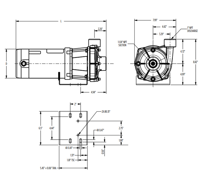
| Model | HP | PH | L (in) | Suction | Discharge | Drain Ports (3) |
|---|---|---|---|---|---|---|
| DR1S05 | 1/2 | 1 | 13.61 | 1-1/4″ NPT | 1″ NPT | 1/4″ |
| DR1S07 | 3/4 | 14.23 | ||||
| DR1S1 | 1 | 15.11 | ||||
| DR1S05 | 1/2 | 3 | 13.08 | |||
| DR1S07 | 3/4 | 13.73 | ||||
| DR1S1 | 1 | 14.08 |

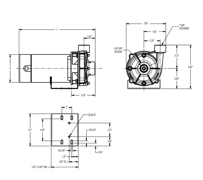
| Model | HP | PH | Enslosure | L (in) | D (in) | Suction | Discharge | Drain Ports (3) |
|---|---|---|---|---|---|---|---|---|
| DR1C05 | 1/2 | 1 | ODP | 17.45 | 5.63 | 1-1/4″ NPT | 1″ NPT | 1/4″ |
| DR1C07 | 3/4 | 17.82 | ||||||
| DR1C1 | 1 | 18.42 | ||||||
| DR1C05 | 3/4 | 1 | TEFC | 16.77 | 7.31 | 1-1/4″ NPT | 1″ NPT | 1/4″ |
| DR1C07 | 1 | 17.02 | ||||||
| DR1C1 | 1-1/2 | 17.52 | ||||||
| DR1C05 | 3/4 | 3 | TEFC | 15.73 | 7.31 | 1-1/4″ NPT | 1″ NPT | 1/4″ |
| DR1C07 | 1 | 17.98 | ||||||
| DR1C1 | 1-1/2 | 17.23 | ||||||
| DR1C05 | 3/4 | 3 – 575v | TEFC | 16.98 | 7.31 | 1-1/4″ NPT | 1″ NPT | 1/4″ |
| DR1C07 | 1 | 17.98 | ||||||
| DR1C1 | 1-1/2 | 17.98 |
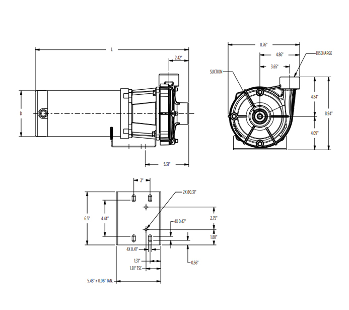
| Model | HP | PH | L (in) | D (in) | Suction | Discharge | Drain Ports (3) |
|---|---|---|---|---|---|---|---|
| DR1J05 | 1/2 | 1 | 15.35 | 5.63 | 1-1/4″ NPT | 1″ NPT | 1/4″ |
| DR1J07 | 3/4 | 16.06 | |||||
| DR1J1 | 1 | 16.17 | |||||
| DR1J05 | 1/2 | 3 | 13.50 | 5.88 | |||
| DR1J07 | 3/4 | 14.00 | |||||
| DR1J1 | 1 | 14.56 |

| Model | HP | PH | L (in) | Suction | Discharge | Drain Ports (3) |
|---|---|---|---|---|---|---|
| DR2S1 | 1 | 1 | 15.48 | 1-1/2″ NPT | 1-1/4″ NPT | 1/4″ |
| DR2S15 | 1-1/2 | 16.23 | ||||
| DR2S2 | 2 | 17.45 | ||||
| DR2S1 | 1 | 3 | 14.45 | |||
| DR2S15 | 1-1/2 | 15.45 | ||||
| DR2S2 | 2 | 16.20 |
| DR2C1 | 1 | 1 | ODP | 18.79 | 5.63 | 1-1/2″ NPT | 1-1/4″ NPT | 1/4″ |
| DR2C15 | 1-1/2 | 19.29 | ||||||
| DR2C2 | 2 | 17.66 | 6.5 | |||||
| DR2C1 | 1-1/2 | 1 | TEFC | 17.86 | 7.25 | 1-1/2″ NPT | 1-1/4″ NPT | 1/4″ |
| DR2C15 | 2 | 18.14 | ||||||
| DR2C2 | 3 | 18.64 | ||||||
| DR2C1 | 1-1/2 | 3 | TEFC | 17.60 | 7.25 | 1-1/2″ NPT | 1-1/4″ NPT | 1/4″ |
| DR2C15 | 2 | 18.85 | ||||||
| DR2C2 | 3 | 19.35 | ||||||
| DR2C1 | 1-1/2 | 3 – 575V | TEFC | 18.35 | 7.25 | 1-1/2″ NPT | 1-1/4″ NPT | 1/4″ |
| DR2C15 | 2 | 18.35 | ||||||
| DR2C2 | 3 | 18.35 |
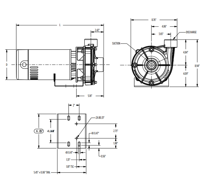
| Model | HP | PH | L (in) | D (in) | Suction | Discharge | Drain Ports (3) |
|---|---|---|---|---|---|---|---|
| DR2J1 | 1 | 1 | 16.55 | 5.63 | 1-1/2″ NPT | 1-1/4″ NPT | 1/4″ |
| DR2J15 | 1-1/2 | 18.15 | |||||
| DR2J2 | 2 | 18.15 | |||||
| DR2J1 | 1 | 3 | 14.94 | ||||
| DR2J15 | 1-1/2 | 16.56 | |||||
| DR2J2 | 2 | 16.56 |

