STAINLESS STEEL SPRINKLER UTILITY PUMP – RJSE-75SS

APPLICATIONS

Ideal for pressure boosting, sprinkler systems, and general purposeapplications where portability and corrosion-resistance isimportant.

FEATURES & BENEFITS

  • Self-priming utility pump designed to lift water up to 25′
  • Corrosion resistant stainless steel pump housing ideal foroperating lawn sprinklers, pressure boosting, and other generalpurpose applications
  • Heavy-duty 3/4 hp 115 Volt motor for years of service andreliability
  • Glass-filled thermoplastic impeller and diffuser for highperformance and efficient water flow
  • Power cord, carry handle, and garden hose adapter included forconvenience and portability
  • Replacement plug kit (#305594001) is available
Click to rate this post!
[Total: 0 Average: 0]

SAFETY WARNINGS

SAFETY WARNINGS – BEFORE OPERATING OR INSTALLING THIS PUMP, READ THIS MANUAL AND FOLLOW ALL SAFETY RULES AND OPERATING INSTRUCTIONS. WARNING – ELECTRICAL PRECAUTIONS All wiring, electrical connections, and system grounding must comply with the National Electrical Code (NEC) and with any local codes and ordinances. Employ a licensed electrician. FOR DUAL VOLTAGE MOTORS Voltage change instructions are located on motor label or on wiring access cover. WARNING – RISK OF ELECTRICAL SHOCK
  • This pump is supplied with a grounding conductor and grounding type attachment plug.
  • To reduce risk of electrical shock, be certain that it is connected only to a properly grounded, grounding-type receptacle.
  • A ground fault interrupter (GFI) protected circuit is recommended for use with any electrical device operating near water.
  • Have an electrician provide an outlet near the point of use. For recommended cable size seeTable 1.
  • Pump and motor must be protected from the weather, for indoor use only.
  • Motor must be grounded and terminal cover in place to reduce electrical shock hazard.
  • Keep motor operating area as dry as possible.
  • Always disconnect power before servicing.
  • Not investigated for use in swimming pool area

APPLICATION

This jet sprinkler pump is a versatile pump for pressure boosting, small underground sprinkler systems, operating lawn sprinklers and a multitude of other general purpose applications. This pump is suitable for installations where the vertical distance from the pump to the water level does not exceed *25 ft. (7.6m), including drawdown. In offset installations, friction losses in the suction pipe must be taken into consideration. (Refer to Table 2, Friction Loss Chart). *Less at high altitudes.

INSTALLATION

a) Pump Location: The pump should be installed in a clean, dry and ventilated location which provides adequate room for servicing and protection from freezing temperatures. It should be bolted to a good foundation, preferably concrete and provided adequate drainage. Locating the pump as close as possible to the water source reduces the friction in the suction pipe and will give maximum capacities. b) Suction pipe: It is recommended that only new, clean 1 inch pipe or hose be used. If the pump is installed any appreciable distance away from the source of water, the suction pipe should be increased to 1-1/4 inch. Horizontal lengths of pipe must gradually slope upwards from the source of water to the pump to avoid air pockets in the line. Thread compound should be used on all pipe joints and connections should be thoroughly tightened. A foot valve must be installed and its operation should be checked since a leak will prevent proper operation of the system. Make sure that the foot valve is located so that it will be submerged at all times. If a sand point or driven well is used, install a check valve next to the pump suction instead of the foot valve. For booster pump applications no foot valve is required. c) Service Line: The service line should be connected as shown in Fig. 1. The size of the service line required is governed entirely by the amount of water needed and the length of the pipe. The pipe selected should be large enough so that the friction loss (determined fromTable 2, Friction Loss Chart) will never exceed a 20 ft (6m) head. CAUTION Undersize wire between the motor and the power source will adversely limit the starting and load carrying abilities of the motor. Minimum wire sizes for the motor branch circuits are recommended in Table 1.

Recommended Wire Gauge For Electrical Cord Length

HP

Volts

0-25 ft.

50 ft.

100 ft.

150 ft.

200 ft.

1/2

115

14

12

10

8

6

sprinkle-installation

Product Info

Model

Item Number

UPC

HP

Amps/Volts

Cord Length

Intake

Discharge

Discharge Pressure PSI at 5′ Lift

Max. Flow (GPM) at 5′

Suction Lift

Max PSI

Max Head

0

10

20

30

40

50

60

Gallons Per Minute

RJSE-75SS

614432

0 10121 14415 6

3/4

6.5/115

8′

1″

1″ FNPT

11

9.5

9

7.3

4.6

2.3

0.4

11

64

147′

Carton Specifications

Model

Length

Width

Height

Weight (lbs)

Carton Cubes (cu ft)

Pallet Quantity

Qty. per Layer

Layers per Pallet

RJSE-75SS

9.8″

15″

11.8″

21

0.69

48

12

4

FRICTION LOSS CHART FOR PLASTIC PIPE:

TABLE 2 – FRICTION LOSS CHART FOR PLASTIC PIPE:
For galvanized pipe, double the figures. Loss of head in feet, due to friction per 100 feet of pipe.

Nominal Pipe Size

U.S. GPM

3/4″

1″

1-1/4”

1-1/2”

2”

4

3.75

1.15

0.30

0.14

5

5.66

1.75

0.46

0.22

6

7.95

2.45

0.65

0.31

7

10.60

3.25

0.86

0.41

8

13.50

4.16

1.10

0.52

9

16.80

5.17

1.35

0.65

10

20.40

6.31

1.67

0.79

0.23

11

24.40

7.58

1.98

0.95

0.27

12

28.60

8.85

2.33

1.10

0.32

14

38.00

11.80

3.10

1.46

0.43

16

48.60

15.10

3.96

1.87

0.55

18

60.50

18.70

4.93

2.33

0.69

20

73.50

22.80

6.00

2.83

0.84

Loss of head in meters, due to friction per 100 meters of pipe.  

Nominal Pipe Size L/Min.

20mm

25mm

32mm

40mm

50mm

15

3.7

1.15

0.30

0.13

20

5.3

1.64

0.43

0.19

25

7.1

2.18

0.56

0.27

30

13.5

4.13

1.08

0.49

35

16.3

5.00

1.31

0.61

40

23.5

7.30

1.90

0.88

0.25

45

28.3

8.74

2.31

1.07

0.29

50

34.2

10.60

2.79

1.32

0.38

55

40.7

12.60

3.32

1.56

0.46

60

48.1

14.90

3.92

1.85

0.54

65

55.7

17.30

4.45

2.15

0.63

70

63.8

19.70

5.20

2.46

0.73

75

72.2

22.40

5.89

2.78

0.83

OPERATION – PRIMING THE PUMP

WARNING: DO NOT RUN THE PUMP BEFORE PRIMING IT, SINCE THE SEAL AND IMPELLER COULD BE PERMANENTLY DAMAGED. 
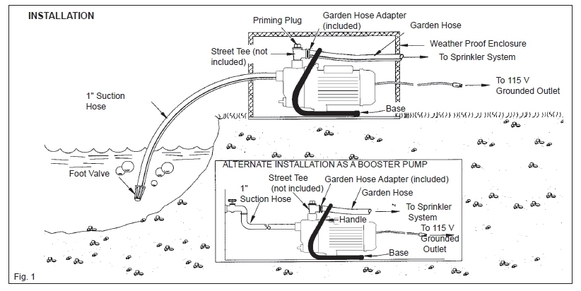
a) Priming: Do not run the pump before priming it, since the seal and impeller could be permanently damaged. Remove the plug from the street tee and pour clean water into the unit until casing and suction line are completely filled. Replace the priming plug and start the motor. If the unit is properly primed, it should pump almost immediately. If not, repeat the priming procedure until all the air has been eliminated from the suction line. If an in-line check valve is used in place of a foot valve, the initial priming time may take 5 to 15 minutes depending on the suction lift, (higher suction lift requires longer priming times). At 10 feet or greater suction lifts, water should be added to the casing approximately every 3 minutes until primed. If the pump does not prime within 25 minutes, stop the pump and check for suction leaks. 
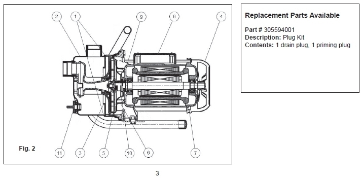
b) Draining: Should the unit be subject to freezing, it will be necessary to drain the pump and tank. To do this, shut off the power to the pump at the main electrical service panel. Open a valve in the system to release the pressure. Remove drain and priming plugs from the casing. Allow ample time for system to drain before reinstalling the plugs!

MAINTENANCE

WARNING – ELECTRICAL PRECAUTIONS All wiring, electrical connections, and system grounding must comply with the National Electrical Code (NEC) and with any local codes and ordinances. Employ a licensed electrician. WARNING – RISK OF ELECTRICAL SHOCK Before servicing motor operated equipment, shut off the power at the main electrical panel and disconnect the power supply from the motor and the accessories. Use safe working practices during servicing of equipment. a) Lubrication: The pump requires none. Refer to motor manufacturer’s instructions for motor lubrication. b) Replacing Mechanical Seal: (See Fig. 2) Disassembly
  1. Shut off the power to the pump at the main service panel and disconnect the power supply from motor.
  2. Open a tap in the water system to release the pressure.
  3. Remove the drain (11) and prime plugs to allow the pump to drain.
  4. Remove the 4 bolts (1) and remove casing (2).
  5. Pry the diffuser (3) out of the casing using 2 slotted screw drivers for leverage.
  6. Remove fan shroud (4) and insert a screwdriver into the slot in the shaft to prevent it from turning while unscrewing the impeller (5) in counter-clockwise direction.
  7. Slip the rotating seal (6) off the shaft.
  8. Remove motor tie bolts (7) and remove motor (8) from adapter (9) by slightly tapping end of motor shaft with a mallet.
  9. Remove the ceramic seal seat (10) from adapter (9).
Reassembly
  1. Clean all the parts thoroughly before assembling.
  2. Push ceramic seal (10) into the adapter (9) using thumbs only. Make sure the smooth surface of the ceramic seat faces outwards.
  3. Reassemble motor (8) to adapter (9) using motor tie bolts (7).
  4. Slip on rotating seal (6) to the shaft with the ‘carbon’ ring towards the ceramic seat.
  5. Replace the impeller (5) and the diffuser (3).
  6. Replace the casing (2) making sure that the o-ring is not damaged and is in place.
  7. Reinstall the drain plugs.
  8. Reconnect the power.
  9. Prime pump, start, check for leaks.
parts-available

TROUBLESHOOTING GUIDE

a) Motor will not start: 1) No power due to blown fuses, open switches or loose connections. b) Pump fails to deliver water: 1) Pump not completely primed. 2) Suction lift is too great. 3) Foot valve is either not submerged, buried in the mud or plugged. c) Pump loses prime: 1) Air leaks in suction line. 2) Well draw down too far. 3) Faulty foot valve. d) Pump delivers water but not at rated capacity: 1) Leaks in suction or discharge line. 2) Foot valve, suction line, impeller or nozzle are partially plugged. 3) Suction lift is greater than recommended. 4) Improper impeller rotation or low speed. 5) Motor does not come off starting windings. 6) Low line voltage at motor.

WANT SOMETHING? REQUEST A QUOTE NOW!